
Electronic Monitoring and Control Solutions

Gas Safety Unit - GSU
Technical Section
To Add To Add
Unit Customisation Customisation
Description Order Code Option 1 Option 2
(Example - A GSU with no customisation option without a Shutdown Button Shroud = 16.008)
(Example - A GSU with no customisation option and a Shutdown Button Shroud = 16.008S)
(Example - A GSU with customisation option 1 = 16.008A)
(Example - A GSU with customisation option 1 and a Shutdown Button Shroud = 16.008AS)
(Example - A GSU with customisation option 2 = 16.008B)
(Example - A GSU with customisation option 2 and a Shutdown Button Shroud = 16.008BS)
GSU 16.008 A B
Wallmount Kit is Included, Extra Wallmount Kit - 10.002
We will be in touch to ask for your pneumatic connection requirements
Additional Mounting Options
Cassette Mounting System - 09.012
Space Saver Cassette Mounting System - 09.013
If a Cassette is ordered we will be in touch to ask if there are
any retrofit bracket requirements with your order.
Our Technical Pages have been enhanced and optimized for Mobile Phone compatibility, this is to allow installers to easily be able to follow our installation procedures on site if required
Shutdown Button Options
We fit Schneider Emergency Shutdown Buttons to our units
these are very high quality ultra reliable safety devices
which have a strong shutdown operation
however you may also require a shutdown button shroud to be fitted if your unit is being installed somewhere the shutdown button may be easily pressed, our shutdown button shrouds are made of high quality metal construction and they are also padlockable for when you are performing maintenance and require a method of ensuring that any control valves connected to your GSU are rendered inoperable. Your GSU will arrive with the shutdown button shroud fitted if ordered.

£49 + VAT
Pneumatic Connections
We are able to supply your GSU with various options of pneumatic connections
3.2mm Rigid Tube
4.0mm Rigid Tube
6.0mm Rigid Tube
Pipe O/D(mm) I/D(mm)
4 2.5mm Nylon Tube
6 4 mm Nylon Tube
3.18 2.18mm Soft Nylon Tube
3.18 2mm Polyurethane Tube
4 2.5mm Soft Nylon and Polyurethane Tube
6 4 mm Soft Nylon and Polyurethane Tube

Electrical Supply
AC Range - 85 to 264V @ 47 TO 440 Hz
AC Current (Typical) 0.03A/230V AC
Fixed 3-Metre long cable supplied with a fused 3A UK 3 pin plug.
Site wire to a double pole switched fused outlet with a 5 Amp fuse

Ultra Low Power
Fuses (Located on PCB)
24V DC Supply Fuse (F1) - 630mA 20 x 5mm Thermal
Internal Mains Supply Fuse (F2) - 2A 20 x 5mm Thermal
Digital Inputs (Non Isolated)
Supply Voltage (provided by GSU) +24V DC
Input Current at 24 V DC 7.2 mA
Inputs compatible with normal dry contact switches, PNP / NPN
Digital Outputs (Dry Contact Volt Free)
Current Rating 0.5A @ 24V DC
Enclosure
Material - ABS
Rating - IP65
Dimensions - 271 x 120 x 170 mm
Colour - Light Grey RAL 7035
Mounting Holes - Accept 4 x M4 screws
ALU is Supplied with a Wall Mounting Kit
Optional Cabinet Mounted Cassette System Available - CLICK HERE for more information.
Design Compliances
Designed in compliance with
-
BS EN 60204-1:2018 Safety of machinery. Electrical equipment of machines
Tested and FULLY compliant with
EN 61326-1:2021 Electrical Equipment for Measurement Control and Lab Use - EMC Requirements.
EN 55011:2016+A2 Conducted RF Emissions
-
EN 55011:2016+A2 Radiated Emissions
-
EN 61000-4-2:2009 Electrostatic Discharge
-
EN 61000-4-3:2006+A2 Radiated Immunity 80 MHz to 6 GHz
-
EN 61000-4-4:2012 Fast Transient and Burst Immunity
-
EN 61000-4-5:2014+A1 Surge Immunity
-
EN 61000-4-6:2014 Conducted RF Immunity
-
EN 61000-4-11:2020 Mains Dips and Interruptions
-
EN 61000-4-8:2010 Power Frequency Magnetic Field Immunity
Mounting (with included Wall Mounting Kit)

Connecting Digital Inputs
The GSU is supplied with Blanking Plugs fitted to maintain sealed integrity, A separate cable gland is supplied for each Digital Input which can be found inside the monitor.
1 With a flat bladed screwdriver insert it into the gap on the right hand clip as shown and either twist or lever the screwdriver to the right to open the clip and you will find the cable glands. 2 With an appropriate screwdriver remove the required blanking plug and using the same seal and nut 3 fit the cable gland, Repeat the procedure to accommodate the amount of Digital Inputs you require

DO NOT remove a blanking plug and fit a cable gland if it is not required as this will result in loss of sealed integrity and may invalidate your warranty.
2


1

Inside you will find the cable glands.
If for any reason the cable glands are missing please contact your supervisor or your installer.
(The M16 cable gland supplied in the kit is generally used for connecting Outputs)
3
Please Note that each input works differently in operation and you must first familiarize yourself with how each input works when in operation to ensure correct required operation if you are wishing to use an input for something else,
Details of how the inputs work in operation can be found on our GSU Overview Page.
It may be useful to fill out a Configuration Sheet for your future reference and also to mark/label your input cables for easy identification, You can download and print an GSU Configuration sheet HERE or from our Downloads page for you to fill out and print or print and fill out to save or file for your future reference.
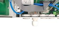
Feed your Input Cable
through your Cable Gland
1

2
We recommend that you
crimp wire ferrules or
bootlace ferrules to the
bare wires


3
Unplug your required
green Input plug
4
Wire your 2 wires into
your green Input Plug
(I/P and 0v) as marked on the PCB


5
Plug your wires back into the
socket and tighten the Cable Gland

If you have a 3-wired device and are unsure how to
establish which 2 wires you need then please use
our simple guide to identify which wires you need
for the correct operation
Which can be found HERE
There may be a situation where your installation does not have all of the sensors listed on the GSU, in this case the alarm/input that you do not require will need to be linked otherwise your GSU will be in alarm condition,
To link the un-required alarm you will need to fit a jumper wire between the I/P and the 0V of the required input
(you can use the AUX input as an example as there is a link fitted as default)
If you would like to use the AUX input as a Shutdown alarm simply remove the wire link and wire your sensor wires to replace the link that you remove (I/P and 0V)

